Logic Gates Symbols and Names: Comprehensive Guide!
Logic gates are essential components used in digital electronics to perform boolean algebra operations on binary signals.
Each type of logic gate has a unique symbol and name that identifies its function, such as inversion, conjunction, disjunction, exclusive disjunction, negation of conjunction, and negation of disjunction.
These gates are NOT, AND, OR, XOR, NAND, and NOR respectively. Knowledge of these symbols and names is foundational for anyone working with or studying digital circuits and systems.
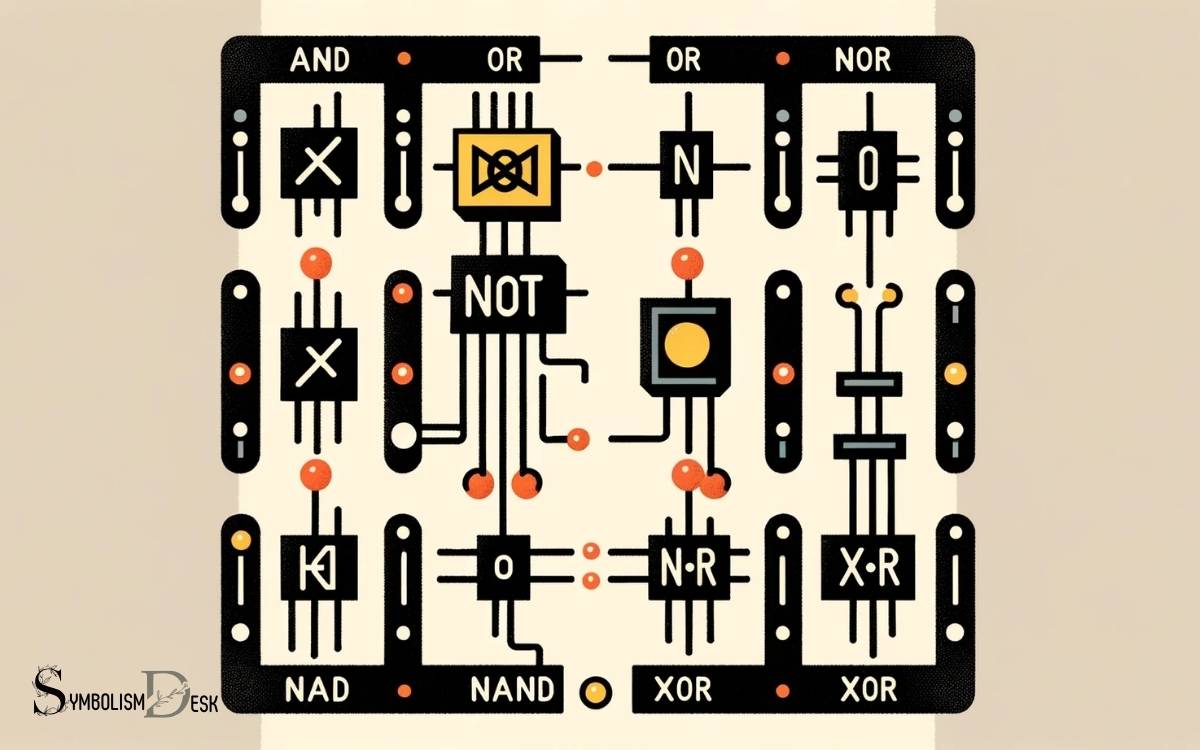
Logic gates are represented by standardized symbols in circuit diagrams to depict their function. For example:
These symbols are part of a visual language used to design and analyze digital circuits. They also help in visualizing how different inputs will produce a specific output according to the rules of binary logic.
Recognizing logic gate symbols and names is the first step in mastering digital circuit design.

Key Takeaway
Logic Gate Symbols and Functions
| Logic Gate | Symbol | Name | Function Description |
|---|---|---|---|
| NOT | ⊕ | Inverter | Inverts the input signal (0 becomes 1, and vice versa) |
| AND | • | Conjunction | Outputs 1 when all inputs are 1, otherwise 0 |
| OR | ≥1 | Disjunction | Outputs 1 when at least one input is 1 |
| XOR | =1 | Exclusive Disjunction | Outputs 1 when the number of 1s in inputs is odd |
| NAND | ⊼ | Negated Conjunction | Outputs 0 only when all inputs are 1 |
| NOR | ⊽ | Negated Disjunction | Outputs 0 when at least one input is 1 |
Understanding Logic Gate Basics
To comprehend the basics of logic gates, it is essential to understand their fundamental operations and functions.
Logic gates are the building blocks of digital electronic circuits, performing Boolean logic operations on one or more input signals to produce a single output.
These operations include AND, OR, NOT, XOR, NAND, and NOR functions. The AND gate outputs a high signal only when all inputs are high, while the OR gate produces a high signal if any input is high.
The NOT gate simply inverts the input signal. The XOR gate outputs a high signal when the number of high inputs is odd.
The NAND gate functions as an AND gate followed by a NOT gate, and the NOR gate acts as an OR gate followed by a NOT gate.
Understanding these basic operations is crucial for comprehending the more complex functions of logic gates in digital systems.
The NOT Gate Symbol and Name
The NOT gate, also known as the inverter, is represented by the symbol of a triangle with a small circle at its input, and its function is to invert the input signal, as discussed in the previous subtopic’s fundamental operations of logic gates.
The key points to note about the NOT gate are:
- Symbol: It is represented by a triangle with a small circle at its input.
- Function: It inverts the input signal, i.e., if the input is high, the output is low, and vice versa.
- Implementation: It can be implemented using transistors or other electronic components.
Understanding the symbol and function of the NOT gate is fundamental to comprehending its role in digital logic circuits.
Exploring the OR Gate Symbol and Name
Exploring the symbol and name of the OR gate, a fundamental logic element in digital circuits, provides insight into its crucial role in logical operations.
The OR gate is represented by the symbol ‘+’ or ‘⊕’ and is often referred to as the ‘logical sum’ or ‘inclusive disjunction’.
Below is a table illustrating the OR gate symbol and name:
| Symbol | Name |
|---|---|
| + | Logical OR |
| ⊕ | Inclusive Disjunction |
The OR gate performs logical addition and outputs a true value if at least one input is true. Understanding the OR gate is fundamental in digital circuit design and forms the basis for more complex logical operations.
The next section will delve into unveiling the AND gate symbol and name, continuing our exploration of logic gate symbols and names.
Unveiling the AND Gate Symbol and Name
The AND gate symbol and name are essential components in digital logic design. Understanding the basics of the AND gate and its corresponding truth table is crucial for building complex logical operations.
This discussion will provide an in-depth look at the AND gate symbol and its function within the realm of logic gates.
And Gate Basics
One fundamental logic gate essential to digital circuitry is the AND gate, represented by a specific symbol and designated by a distinct name.
The AND gate performs an operation that results in a high output (1) only when all of its inputs are high (1).
This gate follows the Boolean expression: Y = A * B, where Y is the output, and A and B are the inputs.
The AND gate symbol consists of two inputs and one output, where the inputs are represented by a small circle and the output by a large semi-circle.
The name “AND” signifies its function of producing an output only when all inputs are true. Understanding the AND gate is crucial for comprehending more complex logic gates and digital circuits.
Understanding Truth Tables
To understand the function and behavior of the AND gate symbol and name, it is essential to examine its corresponding truth table.
The truth table for an AND gate consists of all possible input combinations and their respective outputs.
For an AND gate with two inputs, there are four possible input combinations: 00, 01, 10, and 11. The output will be 0 for the first three combinations and 1 only when both inputs are 1.
This reflects the AND gate’s behavior, where it produces a 1 output only when both inputs are 1; otherwise, it produces a 0.
Understanding the truth table of the AND gate is fundamental in comprehending its logical operation and is crucial for designing and analyzing digital circuits.
Delving Into the XOR Gate Symbol and Name
The XOR gate, also known as the exclusive OR gate, is a digital logic gate that performs an exclusive disjunction. It gives a high output (1) only if the number of high inputs is odd. The truth table for the XOR gate displays its functionality for different input combinations.
XOR Gate Functionality Explanation
Exploring the functionality of the XOR gate involves understanding its unique operation in digital logic circuits.
The XOR gate, or exclusive OR gate, has the following key characteristics:
- The output of the XOR gate is high (1) if the number of high inputs is odd.
- The gate produces a low output (0) if the number of high inputs is even.
- It is distinct from the OR gate, as the XOR gate outputs high only when the inputs are different.
The XOR gate’s functionality is crucial in various applications, including data encryption, error detection, and arithmetic operations in digital systems.
Understanding these fundamental aspects of the XOR gate is essential for its practical implementation in digital circuits.
XOR Gate Truth Table
Analyzing the XOR gate’s truth table provides a comprehensive understanding of its operational characteristics and the relationship between its symbol and name.
The truth table for an XOR gate shows that the output is high (1) when the number of high (1) inputs is odd.
This means that if both inputs are the same, the output is low (0), and if the inputs are different, the output is high (1).
The XOR gate symbol is a variation of the basic OR gate with an additional curved line across the inputs. This symbol visually represents the exclusive nature of the XOR operation.
Understanding the truth table, symbol, and name of the XOR gate is fundamental for grasping its functionality within digital circuits.
Demystifying the NAND Gate Symbol and Name
Demystifying the NAND gate symbol and name involves understanding its unique characteristics and operational principles.
The NAND gate is a fundamental digital logic gate that produces an output that is the inverse of the AND gate.
To comprehend the NAND gate fully, consider the following:
- Symbol: The symbol for a NAND gate consists of two inputs and one output, with the AND gate symbol followed by a small circle at the output, indicating the inversion.
- Truth Table: The truth table for a NAND gate shows that it produces a low output only when all its inputs are high.
- Application: NAND gates are extensively used in digital logic circuits, serving as the basis for universal gates due to their ability to generate any logical function.
Deciphering the NOR Gate Symbol and Name
Deciphering the NOR gate symbol and name involves understanding its distinctive representation and logical function in digital circuits.
The NOR gate is represented by a symbol consisting of two inputs and one output. The inputs are denoted by the small circles, while the output is represented by the standard digital logic gate symbol.
The name “NOR” stands for “NOT OR,” indicating its logical function. The NOR gate produces a high output only when both of its inputs are low. In other words, it gives a low output if any of its inputs are high.
This logical behavior makes the NOR gate a fundamental building block in digital circuit design, commonly used to construct other logic gates and perform various logical operations.
Understanding the NOR gate symbol and name is essential for comprehending its role in digital electronics.
Conclusion
In the intricate world of logic gates, each symbol and name represents a specific function that plays a crucial role in the operation of digital circuits. Just as a conductor directs the movements of an orchestra, logic gates orchestrate the flow of information within a computer.
Understanding the symbols and names of logic gates is akin to deciphering the musical notes on a score, unlocking the harmonious workings of digital technology.


