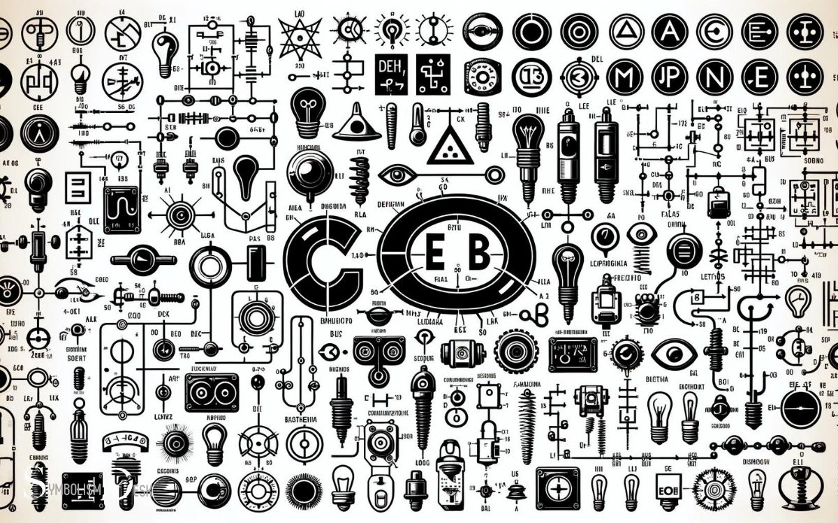
Drawing Electrical Symbols and Names: Related Fields!
The ability to accurately draw and identify electrical symbols is crucial in electrical engineering, electronics, and related fields.
Electrical symbols are the standardized icons used to represent various components and functions within an electrical circuit.
They are the building blocks for electrical schematics and diagrams, enabling professionals to convey complex information efficiently.
Some key points include:
Confidently interpret and create electrical diagrams with a solid grasp of standard electrical symbols and their meanings.

Key Takeaway
Understanding Electrical Symbols
Understanding electrical symbols is essential for anyone working with electrical systems, as they convey important information about components and connections.
These symbols are standardized and universally recognized, serving as a common language for electrical engineers, technicians, and electricians. Each symbol represents a specific electrical component or function, such as a resistor, capacitor, or power source.
For instance, the symbol for a resistor is a zigzag line, while a capacitor is represented by two parallel lines. Additionally, electrical symbols also indicate the type of connection, whether it’s a series connection, parallel connection, or ground connection.
Therefore, having a comprehensive understanding of electrical symbols is crucial for interpreting circuit diagrams, schematics, and blueprints, enabling professionals to design, troubleshoot, and maintain electrical systems effectively.
Commonly Used Electrical Symbols
Understanding commonly used electrical symbols is crucial for interpreting circuit schematics and diagrams. These industry standard symbols convey specific meanings and uses, allowing professionals to accurately comprehend electrical systems.
By familiarizing ourselves with these symbols, we gain the ability to effectively analyze and troubleshoot electrical circuits.
Symbol Meanings and Uses
The application of electrical symbols serves as a fundamental aspect of electrical engineering and design, enabling clear communication and understanding of electrical systems.
Understanding the meanings and uses of commonly used electrical symbols is crucial for professionals in the field.
Here are three key points to consider:
- Clarity: Electrical symbols provide a standardized way to represent components and connections, ensuring that everyone involved in the design and implementation process can easily interpret the schematics.
- Efficiency: The use of symbols streamlines the documentation process, making it easier to create, read, and interpret electrical diagrams, ultimately saving time and reducing the risk of errors.
- Universal Understanding: Electrical symbols are internationally recognized, allowing for seamless communication across different regions and among professionals from diverse backgrounds.
Transition: With a clear understanding of the meanings and uses of commonly used electrical symbols, it is essential to explore industry standard symbols.
Industry Standard Symbols
Analyzing the significance of industry standard symbols in representing electrical components and connections accurately and universally is crucial in electrical engineering and design.
Industry standard symbols provide a common language for representing various electrical components such as resistors, capacitors, inductors, transformers, switches, relays, and more.
These symbols facilitate clear and precise communication, enabling engineers, electricians, and technicians worldwide to interpret electrical schematics and diagrams consistently.
Additionally, they aid in the accurate documentation of electrical systems, ensuring that designs can be easily understood and implemented by different professionals across the industry.
The use of industry standard symbols also helps in standardizing electrical drawings, making them universally recognizable and reducing the likelihood of errors or misinterpretations in the design and implementation of electrical systems.
Understanding Circuit Schematics
A comprehensive grasp of commonly used electrical symbols in circuit schematics is essential for effective electrical engineering and design.
Understanding circuit schematics involves familiarizing oneself with a range of symbols that represent various electrical components and connections.
Here are three key aspects to consider:
- Symbol Recognition: Learning to recognize and interpret symbols for components like resistors, capacitors, diodes, and transistors is fundamental to understanding circuit schematics.
- Connection Representation: Understanding how lines and different types of connections between symbols represent the flow of current and the relationships between components.
- Symbol Variations: Being aware of variations in symbol representation based on different standards or specific circuit requirements is crucial for accurate interpretation and design.
A thorough understanding of these aspects will enable engineers to effectively analyze and design electrical circuits.
Drawing Basic Electrical Symbols
To accurately depict electrical circuits, it is essential to master the drawing of basic electrical symbols. Basic electrical symbols are fundamental representations used in circuit diagrams to illustrate the components and connections within an electrical circuit.
These symbols are standardized across the industry and are crucial for effective communication and understanding among engineers, electricians, and technicians.
Common basic electrical symbols include those for a resistor, capacitor, inductor, switch, relay, transformer, and various types of wires and connections.
Each symbol represents a specific electrical component or function, and understanding how to draw these symbols accurately is fundamental for creating clear and precise circuit diagrams.
Mastery of these symbols facilitates the creation of comprehensive circuit schematics, aiding in the efficient design and troubleshooting of electrical systems.
Interpreting Electrical Symbol Meanings
Understanding the meanings of electrical symbols is essential for accurately interpreting circuit diagrams and schematics.
When interpreting electrical symbol meanings, it’s important to consider:
Standardization: Electrical symbols follow standardized conventions, ensuring consistency across different diagrams and schematics. This standardization allows engineers and technicians to easily understand and interpret the symbols regardless of who created the diagram.
Functionality: Each electrical symbol represents a specific electrical or electronic component and its function within the circuit. Understanding the functionality of each symbol is crucial for comprehending how the components interact and contribute to the overall circuit operation.
Context: Interpreting electrical symbols also requires considering the context of the diagram or schematic. Understanding the surrounding components and their connections helps in accurately deciphering the intended meaning of the symbols.
Advanced Electrical Symbols and Their Functions
Continuing with the exploration of interpreting electrical symbol meanings, it is essential to delve into the complexities of advanced electrical symbols and their functions. Advanced electrical symbols denote intricate components and operations within electrical circuits.
The following table outlines some of the most commonly used advanced electrical symbols and their functions:
| Symbol | Function |
|---|---|
| Transformer | Used to step up or step down voltage in an electrical circuit |
| Capacitor | Stores and releases electrical energy in a circuit |
| Inductor | Provides resistance to changes in current in a circuit |
| Diode | Allows current to flow in only one direction in a circuit |
Understanding these advanced electrical symbols is crucial for accurately interpreting circuit diagrams and schematics. These symbols represent fundamental components that form the basis of complex electrical systems.
Tips for Drawing Electrical Symbols Correctly
When drawing electrical symbols, precision in symbol placement and maintaining consistent symbol sizes are crucial for clarity and accuracy.
Proper placement ensures that the symbols accurately represent the components they depict, while consistent sizing prevents confusion and misinterpretation.
Adhering to these tips will enhance the overall readability and understanding of electrical drawings.
Symbol Placement Precision
Achieving precise symbol placement is essential for accurately representing electrical components in diagrams and schematics.
To ensure correct symbol placement, consider the following tips:
- Consistent Orientation: Maintain uniformity in the orientation of symbols to ensure clarity and ease of understanding for the reader.
- Proportional Spacing: Maintain consistent spacing between symbols to avoid confusion and maintain a clear representation of the circuit layout.
- Logical Flow: Arrange symbols in a logical sequence that follows the flow of current, making it easier for readers to comprehend the circuit’s functionality and operation.
Following these tips will help in accurately representing electrical components in diagrams and schematics, facilitating better communication and understanding of electrical systems.
Consistent Symbol Size
One must ensure that electrical symbols are consistently sized when drawing them to accurately represent components in diagrams and schematics.
Consistent symbol size is crucial for maintaining the clarity and readability of electrical diagrams. When drawing electrical symbols, it is important to adhere to standardized sizes to ensure uniformity and clarity across different diagrams and schematics.
Using consistent symbol sizes also aids in conveying the relative importance or functionality of different components within the electrical system.
Additionally, maintaining uniform symbol sizes facilitates easier interpretation and understanding of the diagrams by technicians, engineers, and other personnel who rely on these visual representations for various purposes.
Therefore, paying attention to the consistent sizing of electrical symbols is essential for creating accurate and comprehensible electrical diagrams and schematics.
Conclusion
Drawing electrical symbols is an essential skill for anyone working in the field of electrical engineering. Understanding and interpreting these symbols is crucial for designing and troubleshooting electrical systems.
It is estimated that there are over 100 different electrical symbols commonly used in engineering drawings, each with its own specific meaning and function.
Mastering the art of drawing electrical symbols accurately is fundamental for success in the field of electrical engineering.


