74ls Gate Symbols and Names: AND!
74LS logic gates, part of the 7400 series of integrated circuits, come with standardized symbols and names that are crucial for digital electronics design and analysis.
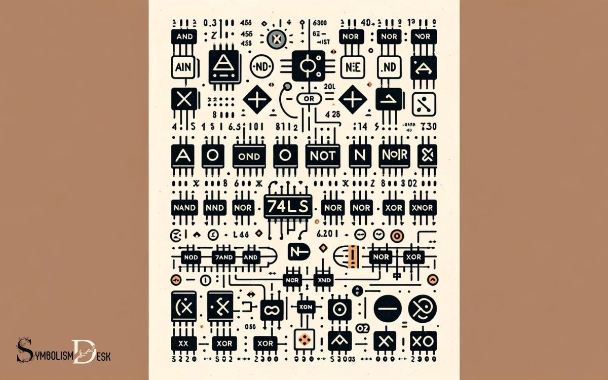
These gates include AND, OR, NOT, XOR, NAND, and NOR, each with a unique symbol to denote its function in schematic diagrams.
Understanding these symbols and names is vital for anyone involved in the creation or interpretation of digital circuitry.
The 74LS series is a subset of the broader 7400 series, with “LS” indicating “Low-power Schottky”, a technology that combines low power consumption with high speed.
Each logic gate performs a fundamental operation on one or more binary inputs to produce a single binary output.
Here’s a quick rundown:
These logical operations are represented by distinct symbols in circuit diagrams, making it easy to identify the type of logic being implemented at a glance.
Mastering 74LS logic gate symbols is a foundational skill for digital electronics enthusiasts and professionals alike.

Key Takeaway
Understanding 74LS Gate Symbols
Discussing the understanding of 74LS gate symbols involves analyzing their functional representations and applications within digital circuitry.
The 74LS series of integrated circuits are popular for their use in various digital applications. These gate symbols represent different logic functions such as AND, OR, NOT, NAND, and NOR gates.
Each gate symbol has a unique graphical representation, and understanding their logic operation is crucial for designing and troubleshooting digital circuits.
The 74LS gate symbols are essential components in digital electronics, enabling the manipulation of binary data through logical operations.
These symbols are fundamental building blocks in digital circuit design and are widely used in microprocessor and microcontroller-based systems. Understanding their functionality is vital for engineers and hobbyists working with digital electronics.
Basic Logic Gates Overview
An understanding of 74LS gate symbols sets the foundation for comprehending the basic logic gates and their applications in digital circuitry. Basic logic gates are the building blocks of digital electronics, performing fundamental logical functions in digital circuits.
Here are three essential points to consider in the overview of basic logic gates:
- Types of Basic Logic Gates: The basic logic gates include AND, OR, NOT, NAND, NOR, and XOR gates, each serving a specific logical function.
- Operation and Truth Tables: Each logic gate has a unique truth table that defines its operation based on input and output combinations, providing a clear understanding of its behavior.
- Application in Digital Circuits: Basic logic gates are extensively used in digital circuit design, forming the basis for more complex digital systems and processors.
74LS AND Gate Symbol and Name
The LS AND gate symbol and name are fundamental components in digital logic design. Understanding the symbol representation and explanation, as well as the 74LS AND gate and naming convention, is crucial for designing and analyzing logic circuits.
This discussion will provide clarity and insight into the key aspects of LS AND gate symbols and names.
Symbol Representation Explanation
Explaining the LS AND gate symbol and its name is essential for understanding its function in digital circuit design.
- Symbol Representation: The LS AND gate is represented by a symbol with two inputs and one output. The inputs are usually labeled A and B, and the output is labeled Y.
- Logic Function: The symbol represents the logical operation where the output is high (usually denoted as 1) only when both inputs are high. Otherwise, the output is low (usually denoted as 0).
- Name Significance: The name “LS AND gate” signifies that it is a Low-power Schottky (LS) integrated circuit component performing the AND operation, which is a fundamental function in digital logic design.
74LS AND Gate
Symbolizing the logical operation of two inputs and one output, the LS AND gate plays a crucial role in digital circuit design.
The LS AND gate symbol consists of two inputs and one output, with the logical AND operation being performed on the inputs to produce the output. It is represented by the familiar AND gate symbol, which consists of a small circle at the intersection of the input lines.
The LS AND gate is a fundamental building block in digital logic design, where it is used to combine multiple input signals to produce a single output based on the logical conjunction of the inputs.
Understanding the LS AND gate symbol and its function is essential for anyone involved in digital circuit design and implementation.
Naming Convention Clarification
When clarifying the naming convention for the LS AND gate symbol and name, it is important to understand the precise significance and representation of each component.
- LS: The “LS” in the naming convention stands for “Low-Power Schottky,” indicating the specific technology used in the gate’s construction.
- AND Gate Symbol: The symbol for the LS AND gate consists of two input terminals and one output terminal, with the logical AND operation represented by the internal circuitry.
- Naming Convention: The naming convention for the LS AND gate follows industry standards, with the prefix “LS” denoting the gate’s technology and the following term indicating its function as an AND gate.
Understanding these components of the naming convention is crucial for accurately identifying and utilizing LS AND gates in electronic circuit design.
74LS OR Gate Symbol and Name
The LS OR gate symbol is commonly represented as a triangle with a curve at the bottom, and its name is derived from its function in logic circuitry.
The LS OR gate, also known as the Low Power Schottky OR gate, is a digital logic gate with two or more inputs and one output. It performs logical disjunction based on the inputs, where the output is true if at least one of the inputs is true.
The truth table for a 2-input LS OR gate is as follows:
| Input A | Input B | Output |
|---|---|---|
| 0 | 0 | 0 |
| 0 | 1 | 1 |
| 1 | 0 | 1 |
| 1 | 1 | 1 |
This gate is vital in digital electronics for performing logical operations and is widely used in various electronic circuits.
74LS NOT Gate Symbol and Name
The LS NOT gate, also known as the Low Power Schottky NOT gate, is an essential digital logic gate with a single input and one output. It is widely used in electronic circuits for signal inversion.
The following are key points about the LS NOT gate:
- Symbol: The LS NOT gate is represented by a triangle pointing to the right with a small circle at its tip, indicating the inversion of the input signal.
- Functionality: It produces an output that is the logical negation of its input. If the input is high, the output is low, and vice versa.
- Application: It is used in conjunction with other logic gates to perform various logical operations in digital circuits, such as in microprocessors, memory units, and more.
74LS XOR Gate Symbol and Name
The LS XOR gate, represented by the 74LS XOR symbol, plays a crucial role in digital logic circuits. Its name, XOR, stands for exclusive OR, and it performs the function of outputting true only when the number of true inputs is odd.
Understanding the symbol, name, and function of the 74LS XOR gate is essential for designing and analyzing complex electronic systems.
74LS XOR Symbol
The LS XOR symbol represents the exclusive OR gate, denoting a logic function that produces an output of 1 only when its two inputs differ.
The LS XOR gate symbol is represented as follows:
- Symbol: ⊕
- Truth table: | A | B | A ⊕ B | |—|—|——-| | 0 | 0 | 0 | | 0 | 1 | 1 | | 1 | 0 | 1 | | 1 | 1 | 0 |
- Function: The output is high (1) when the inputs are different, and low (0) when the inputs are the same.
The LS XOR gate, also known as the exclusive OR gate, is an essential component in digital electronics, used for various applications such as arithmetic operations, error detection, and data transmission.
Name for XOR
How is the XOR gate symbol and name represented in LS gate terminology? In LS gate terminology, the XOR gate is represented by the symbol ⊕ and is referred to as the “exclusive OR” gate.
This gate performs the exclusive disjunction operation, yielding a true output only when the number of true inputs is odd.
The name “exclusive OR” indicates that the gate produces a true output when the number of true inputs is exclusively one. This name distinguishes it from the standard OR gate, which produces a true output when at least one input is true.
The LS gate XOR symbol and name are fundamental in digital logic circuits, enabling the implementation of various logical functions and operations.
74LS XOR Function
In LS gate terminology, the symbol and name for the XOR gate are fundamental for implementing various logical functions and operations.
The XOR gate is represented by the symbol ⊕ and is referred to as the Exclusive OR gate. This gate produces a high output (1) only if the number of inputs that are high is odd.
It is a binary operation that gives a true (1 or HIGH) output when the number of true inputs is odd. The LS XOR gate is widely used in digital systems, including arithmetic circuits, error detection, and data transmission.
It plays a crucial role in modern computing and is essential for creating complex logical operations and functions.
74LS NAND Gate Symbol and Name
When designing digital circuits, it is essential to understand the LS NAND gate symbol and its corresponding name.
The LS NAND gate is a fundamental logic gate that performs the operation of the logical AND followed by a logical NOT. It is represented by the symbol shown below and is commonly used in various digital applications.
| Input A | Input B | Output |
|---|---|---|
| 0 | 0 | 1 |
| 0 | 1 | 1 |
| 1 | 0 | 1 |
| 1 | 1 | 0 |
Understanding the LS NAND gate symbol and its truth table is crucial for designing and analyzing digital circuits. Its versatility and usefulness make it a vital component in digital logic design.
74LS NOR Gate Symbol and Name
The LS NOR gate symbol and its corresponding name represent another essential component in digital circuit design, continuing the exploration of logic gates from the previous subtopic on the LS NAND gate.
The LS NOR gate serves crucial functions in digital logic design, including Boolean algebra and the construction of more complex logic circuits.
Its symbol and name are standardized representations that enable engineers and designers to easily incorporate it into circuit diagrams and schematics.
Understanding the LS NOR gate’s symbol and name is paramount for anyone working with digital logic circuits, as it forms the basis for logical operations in various electronic devices.
By mastering the LS NOR gate symbol and name, individuals can effectively analyze and design digital systems with improved efficiency and accuracy.
Conclusion
The 74LS gate symbols and names are essential components in digital circuit design. Understanding the symbols and names of basic logic gates such as AND, OR, NOT, XOR, NAND, and NOR is crucial for engineers and students in the field of electronics.
These symbols represent the functions and operations of these gates, allowing for efficient and effective circuit design and implementation.
As the gates work together, they form the building blocks of complex digital systems, creating a network of interconnected pathways for data flow.


